利用Arduino可以偵測與控制PC風扇,
本文介紹如何讀取風扇轉速的第一種方式。
之前在PC風扇研究中有說過3pin 4pin風扇可提供
轉速偵測功能,請參考本文。
現在就來實做使用Arduino來偵測風扇轉速。
其實Arduino官網就有一篇文章介紹如何讀取風扇轉速了:
https://playground.arduino.cc/Main/ReadingRPM
裡面也有提供範例程式:
//-----------------------------------------------
volatile byte half_revolutions;
unsigned int rpm;
unsigned long timeold;
 void setup()
 {
   Serial.begin(9600);
   attachInterrupt(0, rpm_fun, RISING);
   half_revolutions = 0;
   rpm = 0;
   timeold = 0;
 }
 void loop()
 {
   if (half_revolutions >= 20) {
     //Update RPM every 20 counts, increase this for better RPM resolution,
     //decrease for faster update
     rpm = 30*1000/(millis() - timeold)*half_revolutions;
     timeold = millis();
     half_revolutions = 0;
     Serial.println(rpm,DEC);
   }
 }
 void rpm_fun()
 {
   half_revolutions++;
   //Each rotation, this interrupt function is run twice
 }
//-----------------------------------------------
程式說明
這個程式我測試過,但我覺得使用效果不好,分析一下原因:
將風扇tach轉速輸出腳接到interrrupt pin0,也就是我上面標色的那段程式碼,
實際上int0這隻腳是與D2共用的腳位,這裡設定為中斷0輸入。
然後轉速每20轉後會利用millis()這個時間常數去計算時間差,
並換算成每分鐘的轉速,也就是RPM,再輸出到com port介面。
其中重要的幾個部份再加以說明
attachInterrupt(0, rpm_fun, RISING);
以上這行就是Arduino中重要的中斷程式,
Arduino有兩個硬體外部中斷腳位,這是固定的,如下圖:
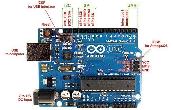
interrupt(中斷) 0,位置在右上方D2
interrupt(中斷) 1,位置在右上方D3
重要語法解析
attachInterrupt(中斷位址, isr中斷服務程式名稱, 觸發條件);
中斷位址就是上圖的interrupt0跟1,其他IC有比較多的中斷腳位,UNO就只有這兩個中斷而已。
isr是中斷服務常式的縮寫:Interrupt Service Routine,中斷發生之後要跳去執行的程式。
觸發條件是決定是否符合觸發發生的模式,共有這幾種:
LOW : Pin在低電位時觸發中斷
CHANGE : Pin值改變時觸發中斷
RISING : Pin由LOW變成HIGH時觸發中斷
FALLING : Pin由HIGH變成LOW時觸發中斷
attachInterrupt(0, rpm_fun, RISING);
上述這句程式的解析就是使用interrupt 0(D2 pin),中斷服務常式的名稱為rpm_fun,上緣觸發
在PC風扇是由intel規範了轉速輸出的定義:

其中規範了每轉一次要送出兩個pulse(脈波)訊號, 所以使用上緣或下緣或是low來做觸發條件
其實對轉速量測都沒有差別,有興趣可自行實驗。
底下是我改寫後,將轉速輸出到1602A液晶螢幕上的程式:
/*
使用1602A I2C LCD模組及函式庫
使用Interrupt 0 讀取風扇轉速並顯示在1602A LCD螢幕上
LCD I2C Library,從這裡可以下載:
https://bitbucket.org/fmalpartida/new-liquidcrystal/downloads
本程式使用Newliquidcrystal_1.3.5版函式庫
作者:Lu yaku
日期:2018.04.25
*/
#include <Wire.h>
#include <LiquidCrystal_I2C.h>
// 初始化 I2C 1602A LCD,I2C預設地址為0x27
LiquidCrystal_I2C lcd(0x27, 2, 1, 0, 4, 5, 6, 7, 3, POSITIVE);
volatile byte rpmcount;
unsigned int rpm;
unsigned long timeold;
void rpm_fun()
{
rpmcount++;
}
void setup() {
lcd.begin(16, 2);
// 閃爍三次
for(int i = 0; i < 3; i++) {
lcd.backlight(); // 開啟背光
delay(250);
lcd.noBacklight(); // 關閉背光
delay(250);
}
lcd.backlight();
delay(250);
// 輸出初始化文字
lcd.setCursor(0, 0); // 設定游標位置在第一行行首
lcd.print("Hello, world!");
delay(1000);
lcd.setCursor(0, 1); // 設定游標位置在第二行行首
lcd.print("LCD is Working!");
delay(2000);
lcd.clear();
lcd.setCursor(0, 0);
lcd.print("FAN Speed");
//Interrupt 0 是數位pin 2
//Triggers on FALLING (下緣觸發,high到low時觸發)
attachInterrupt(0, rpm_fun, FALLING);
rpmcount = 0;
rpm = 0;
timeold = 0;
}
void loop() {
delay(1000);
detachInterrupt(0);
rpm = 30*1000/(millis() - timeold)*rpmcount;
timeold = millis();
rpmcount = 0;
lcd.setCursor(0, 1);
lcd.print(rpm);
lcd.setCursor(5, 1);
lcd.print("rpm");
//Restart the interrupt processing
attachInterrupt(0, rpm_fun, FALLING);
}
接線圖

相關照片
整體測試環境,測試風扇是intel 775的標準風扇:

轉速輸出:

之前購買的7電行動電源可調版,輸出最高能調為13V,測試時設定為12V,測試過程中可調高低:


 留言列表
留言列表