1602A用並聯匯流排的問題在於太耗I/O腳位了,不管是8位元還是4位元,
最起碼要用上6個IO pin腳,如果還要做其他應用的話,容易顯得捉襟見肘,
所以就有人陸續改造成串連方式使用。
我手上使用的工具書--旗標的超圖解Arduino互動設計入門就有提到使用
74LS164 shift register這顆IC來將串列資料轉成並列資料給1602來使用,
電路圖:

另外也有人用74HC595這顆IC來做串並列資料轉換,電路圖:

使用74LS164的優點是只要兩根I/O pin腳就好,而使用74HC595則需要三根I/O pin腳,
但74HC595的優點是傳輸速度較快。
而另一個更好的解決方法是使用 I2C bus,只要兩根pin腳,還能夠將很多裝置都透過同一個
bus共同使用,每個裝置都有自己的address,所以不會打架,i2C bus架構圖如下:
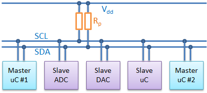
SCL跟SDA兩線上可以並聯許多裝置共用同一個bus,只要使用不同定址位置區分不同裝置即可。
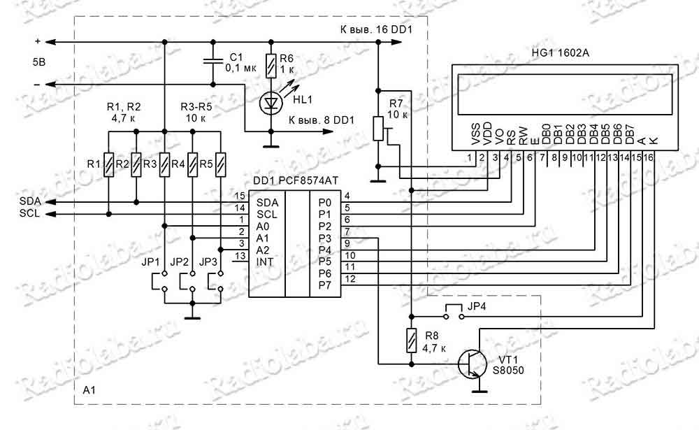
而底下是I2C bus轉1602A的電路圖:
因為有這樣的優點,所以現在市面上也有廠商製作成模組販售,甚至直接提供販售焊好模組的LCD,
有需要的話請在各大網拍或電子商城選購。
底下是模組實體照片:

下圖是A0-A2共八種地址的設定方式,也就是上圖JP1-JP3,實體照片上標示的A0 A1 A2
如照片上顯示的,A0-A2都是空接,也就是high,所以預設地址是0x27:

如果你買到的模組IC是用8574AT的話,則預設地址是0x3F,原因如下:

如果IC上的字太小難以辨識的話,可以用另文的I2C scanner程式去掃描找出正確的位置。
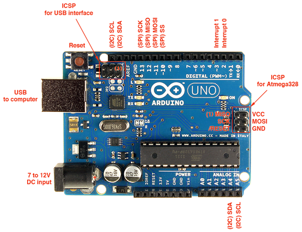
底下是Arduino UNO的各接腳圖,I2C可以接右下或左上,都可以通用。
串列式不管是74LS164或是I2C都不在IDE預設支援中,不過網路上有很多提供相關函式庫的地方,
我建議從這裡下載:
https://bitbucket.org/fmalpartida/new-liquidcrystal/downloads/
目前最新版本是1.3.5,日期是2011-11-26
下載ZIP檔案解壓縮後會有兩個子目錄,其中一個是給MACOS用的,
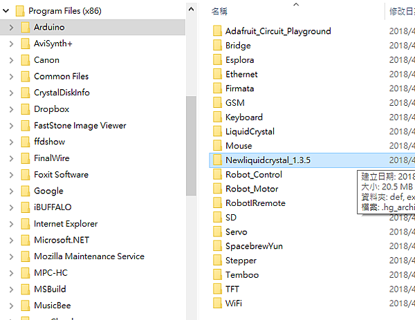
PC用的目錄名稱是Newliquidcrystal_1.3.5,將整個資料夾搬到arduino程式目錄下的libraries目錄,
相關位置如下圖:
重啟arduino開發程式之後就能看到新的函式庫與範例程式,如下圖:
使用74LS164的串列方式可以選擇HelloWorld_SR這個範例程式,如下:
#include <Wire.h>
#include <LiquidCrystal_SR.h>
LiquidCrystal_SR lcd(8,7,TWO_WIRE);
// | |
// | \-- Clock Pin
// \---- Data/Enable Pin
// Creat a set of new characters
byte armsUp[8] = {0b00100,0b01010,0b00100,0b10101,0b01110,0b00100,0b00100,0b01010};
byte armsDown[8] = {0b00100,0b01010,0b00100,0b00100,0b01110,0b10101,0b00100,0b01010};
void setup(){
lcd.begin(16,2); // initialize the lcd
lcd.createChar (0, armsUp); // load character to the LCD
lcd.createChar (1, armsDown); // load character to the LCD
lcd.home (); // go home
lcd.print("LiquidCrystal_SR");
}
void loop(){
// Do a little animation
for(int i = 0; i <= 15; i++) showHappyGuy(i);
for(int i = 15; i >= 0; i--) showHappyGuy(i);
}
void showHappyGuy(int pos){
lcd.setCursor ( pos, 1 ); // go to position
lcd.print(char(random(0,2))); // show one of the two custom characters
delay(150); // wait so it can be seen
lcd.setCursor ( pos, 1 ); // go to position again
lcd.print(" "); // delete character
}
紅色那兩行表示要include的函式庫,藍色則是指定兩個IO pin腳,
一個是clock腳另一個是data/enable腳。
後續的函式使用則與並列式的語法一樣。
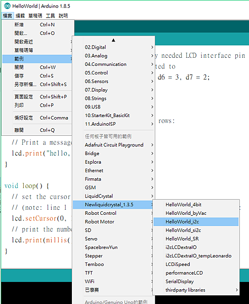
使用I2C的串列方式可以選擇HelloWorld_i2c這個範例程式,如下:
#include <Wire.h>
#include <LiquidCrystal_I2C.h>
#define BACKLIGHT_PIN 13
LiquidCrystal_I2C lcd(0x38); // Set the LCD I2C address
//LiquidCrystal_I2C lcd(0x38, BACKLIGHT_PIN, POSITIVE); // Set the LCD I2C address
// Creat a set of new characters
const uint8_t charBitmap[][8] = {
{ 0xc, 0x12, 0x12, 0xc, 0, 0, 0, 0 },
{ 0x6, 0x9, 0x9, 0x6, 0, 0, 0, 0 },
{ 0x0, 0x6, 0x9, 0x9, 0x6, 0, 0, 0x0 },
{ 0x0, 0xc, 0x12, 0x12, 0xc, 0, 0, 0x0 },
{ 0x0, 0x0, 0xc, 0x12, 0x12, 0xc, 0, 0x0 },
{ 0x0, 0x0, 0x6, 0x9, 0x9, 0x6, 0, 0x0 },
{ 0x0, 0x0, 0x0, 0x6, 0x9, 0x9, 0x6, 0x0 },
{ 0x0, 0x0, 0x0, 0xc, 0x12, 0x12, 0xc, 0x0 }
};
void setup()
{
int charBitmapSize = (sizeof(charBitmap ) / sizeof (charBitmap[0]));
// Switch on the backlight
pinMode ( BACKLIGHT_PIN, OUTPUT );
digitalWrite ( BACKLIGHT_PIN, HIGH );
lcd.begin(16,2); // initialize the lcd
for ( int i = 0; i < charBitmapSize; i++ )
{
lcd.createChar ( i, (uint8_t *)charBitmap[i] );
}
lcd.home (); // go home
lcd.print("Hello, ARDUINO ");
lcd.setCursor ( 0, 1 ); // go to the next line
lcd.print (" FORUM - fm ");
delay ( 1000 );
}
void loop()
{
lcd.home ();
// Do a little animation by writing to the same location
for ( int i = 0; i < 2; i++ )
{
for ( int j = 0; j < 16; j++ )
{
lcd.print (char(random(7)));
}
lcd.setCursor ( 0, 1 );
}
delay (200);
}
可以注意到,不同的串列介面引用的函式庫就不一樣,這點在除錯時可以注意是不是有錯誤,
藍色那一列是要指定I2C位置給函式庫,依照上一篇I2C scanner掃描結果,
I2C模組位置應該改為0x27。位址一定要對指令才能正確傳送到LCD模組。
而Arduino的I2C介面腳位是固定的,所以不須像並列介面或74LS16一樣要指定IO接腳。
更新:
經實測上面I2C範例對我所選購的I2C模組是有問題的,可編譯但執行後功能不正確,
問題出在
LiquidCrystal_I2C lcd(0x27); 這一行,必須改成下面格式才能正確顯示:
LiquidCrystal_I2C lcd(0x27, 2, 1, 0, 4, 5, 6, 7, 3, POSITIVE);
而且背光的開啟用軟體指令即可,不需要用硬體pin腳控制,所以可以拿掉
BACKLIGHT_PIN這個設定。
修改後完整程式如下,可以順利編譯與執行:
#include <Wire.h>
#include <LiquidCrystal_I2C.h>
//#define BACKLIGHT_PIN 13
//LiquidCrystal_I2C lcd(0x38); // Set the LCD I2C address
LiquidCrystal_I2C lcd(0x27, 2, 1, 0, 4, 5, 6, 7, 3, POSITIVE);
//LiquidCrystal_I2C lcd(0x38, BACKLIGHT_PIN, POSITIVE); // Set the LCD I2C address
// Creat a set of new characters
const uint8_t charBitmap[][8] = {
{ 0xc, 0x12, 0x12, 0xc, 0, 0, 0, 0 },
{ 0x6, 0x9, 0x9, 0x6, 0, 0, 0, 0 },
{ 0x0, 0x6, 0x9, 0x9, 0x6, 0, 0, 0x0 },
{ 0x0, 0xc, 0x12, 0x12, 0xc, 0, 0, 0x0 },
{ 0x0, 0x0, 0xc, 0x12, 0x12, 0xc, 0, 0x0 },
{ 0x0, 0x0, 0x6, 0x9, 0x9, 0x6, 0, 0x0 },
{ 0x0, 0x0, 0x0, 0x6, 0x9, 0x9, 0x6, 0x0 },
{ 0x0, 0x0, 0x0, 0xc, 0x12, 0x12, 0xc, 0x0 }
};
void setup()
{
int charBitmapSize = (sizeof(charBitmap ) / sizeof (charBitmap[0]));
// Switch on the backlight
//pinMode ( BACKLIGHT_PIN, OUTPUT );
//digitalWrite ( BACKLIGHT_PIN, HIGH );
lcd.begin(16,2); // initialize the lcd
for ( int i = 0; i < charBitmapSize; i++ )
{
lcd.createChar ( i, (uint8_t *)charBitmap[i] );
}
lcd.home (); // go home
lcd.print("Hello, ARDUINO ");
lcd.setCursor ( 0, 1 ); // go to the next line
lcd.print (" FORUM - fm ");
delay ( 1000 );
}
void loop()
{
lcd.home ();
// Do a little animation by writing to the same location
for ( int i = 0; i < 2; i++ )
{
for ( int j = 0; j < 16; j++ )
{
lcd.print (char(random(7)));
}
lcd.setCursor ( 0, 1 );
}
delay (200);
}


 留言列表
留言列表